TTCM
|
TTCM is a Trigger, Timing and Control Module for VMEDAQ system. It is a 6U VME64x slave module. TTCM has onboard 40 MHz clock generator that is used for clock source for TTC bus. TTCM has NIM level LEMO inputs for spill and 7 trigger signals and 32 ECL/LVDS inputs for trigger signals. Two NIM level LEMO outputs are software programmable.
Front Panel Interface
|
TTC Bus Output
TTC bus output provides clock, spill, trigger and reset LVDS signals. It is compatible with VMEDAQ specification.
LEDs
- 1 (red) - lights on spill when data readout is enabled
- 2 (yellow) - blinks on blocked triggers (dead time)
- 3 (green) - blinks on triggers being read out
Inputs
- NIM1..NIM7 - Trigger inputs, NIM standard, 5 ns minimum
- SPILL - external sync signal, positive logic. Readout enabled with logic one on this input.
- LVDS1..LVDS32 - Trigger inputs, LVDS or ECL, 5 ns minimum
Outputs
- OUT1 - NIM, spill output
- OUT2 - NIM, BRIC clock
- P12 internal connector - aux. TTC output
TTCM VME Interrupt Lines
- IRQ1 - data read XOFF input
- IRQ2 - spill output
- IRQ5 - data read request output
VME Registers
Detailed description of TTCM VME Registers
VME Data Format
Trigger Cable
For use with TQDC-16, special ribbon twisted pair cable is supplied with 34-pin connector on one side and four 10-pin connectors on other side. One cable connects four TQDC-16 modules with TTCM.
Input Aggregation
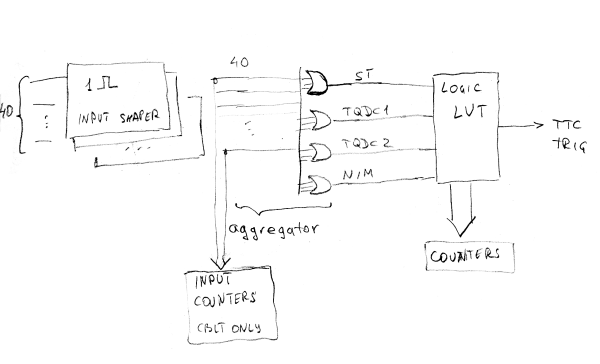
Trigger inputs are combined after shaping and delay by OR scheme. 40 inputs are reduced to 4 trigger lines. Logic OR is performed this way (trigger line = input OR input ...):
- ST = LVDS1
- TQDC1 = LVDS6 | LVDS10 | LVDS14
- TQDC2 = LVDS18 | LVDS22 | LVDS26 | LVDS30
- NIM = NIM1 | ... | NIM7
Trigger Logic Delay
Measured delay from NIM input to TTC bus output: min. 530 ns, max. 580 ns. Due to 20 MHz sampling the delay is varied by 50 ns. this applies to TTCM firmware 1.0.10604
TTC Bus
See TTC for details.
P12 TTC Connector
Internal P12 connector is duplicating the front-panel TTC output. Even signal pin positive.
pin pair |
signal |
description |
1-10 |
reserved |
don't use |
11, 12 |
trigger |
trigger signal |
13, 14 |
spill |
Trigger and data readout enable |
19, 20 |
ground |
signal ground |
TTCM Block Diagram

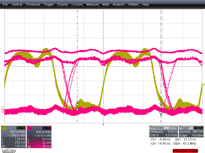
TTC Output Signals


